

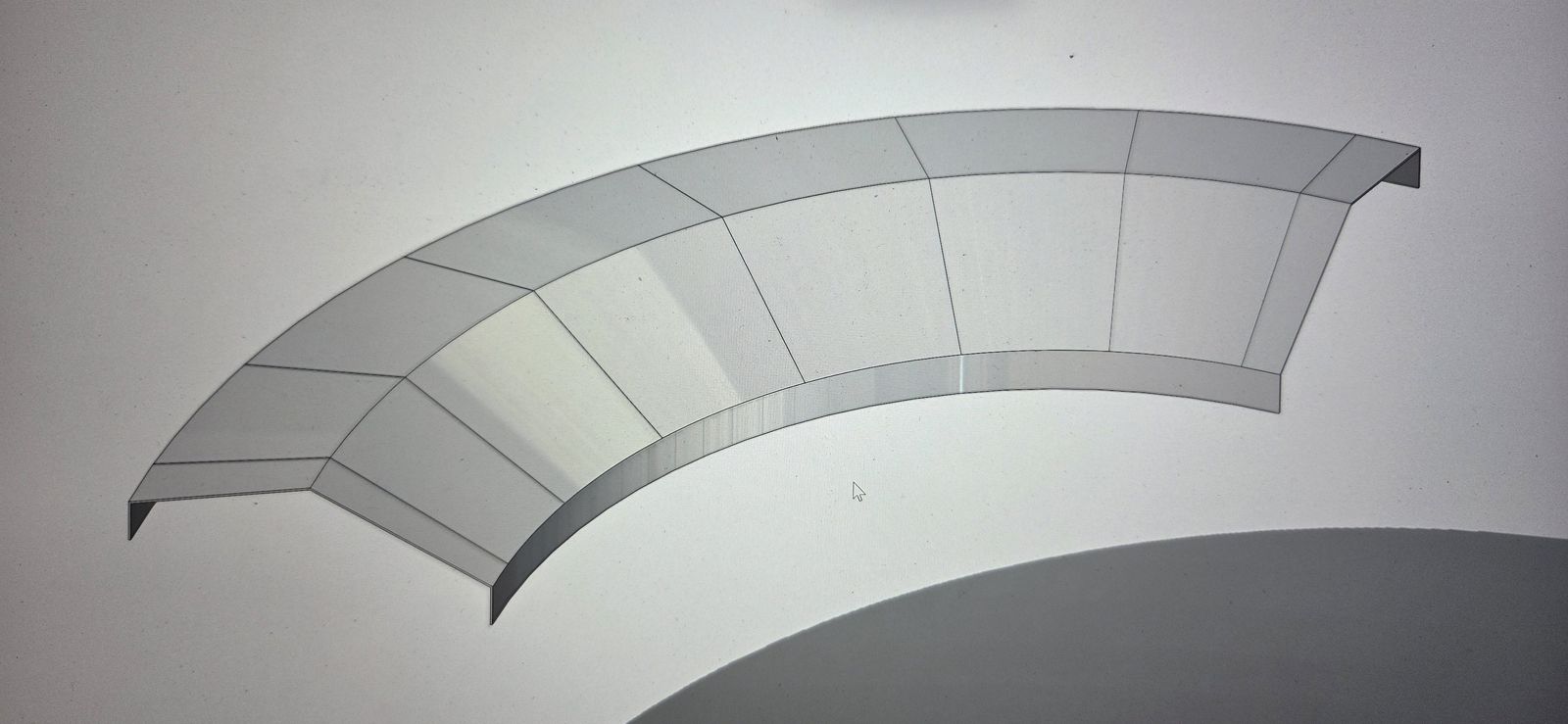
Bend radius and flange chart
Design bends we can form the first time.
Every bend has a smallest inside radius the material will take without cracking, and every flange has a shortest length the press brake can hold. Design to these and your part forms cleanly, with no surprises at the first article.
Minimum inside bend radius
As a multiple of material thickness (T):
| Material | Minimum inside radius | Notes |
|---|---|---|
| Mild steel (hot or cold rolled) | 1 × T | Bends easily in any direction |
| Galvanized steel | 1 × T | Tight radii can flake the zinc coating |
| 304 and 316 stainless steel | 1 to 1.5 × T | Springs back more than mild steel |
| 5052-H32 aluminum | 1 to 1.5 × T | The usual choice for formed aluminum parts |
| 6061-T6 aluminum | 2 to 3 × T | Cracks on tight bends; bend across the grain |
| Plate over 1/4 inch | 1.5 to 2 × T | Depends on the grade and the bend direction |
Shortest flange
A flange needs enough length to sit across the die while it is formed. As a rule of thumb, make every flange at least 4 × T plus the inside radius, measured to the outside of the bend. Shorter flanges are possible with special tooling; ask us before you design them in.
Holes and cut-outs near a bend
- Keep holes at least 2.5 × T plus the bend radius from a bend, or they will stretch out of round.
- Keep holes at least 2 × T from an edge.
- Add a bend relief, a small notch at least T wide, where a bend meets an edge.
- Make holes at least the material thickness in diameter.
Press brake capacity
We form on press brakes up to 175 ton by 10 feet and 350 ton by 12 feet, with various tooling for complex geometries. For a long or heavy part, tell us the bend length and the thickness and we will check it against the tonnage needed.
Tolerances on formed parts
Typical, unless your drawing says otherwise: ±0.010 inch (±0.25 mm) on a flat cut feature, ±0.020 inch (±0.5 mm) across one bend, and ±1° on bend angles. Tolerances stack up across bends, so dimension critical features from one datum. Tighter tolerances are possible; put them on the drawing and we will quote to them.
See also the sheet metal gauge chart and designing sheet metal parts.
Have a part in mind?
Send us your drawings, models or a sketch. We will come back with a plan and a quote. Or call 519-218-9525.
Send us your drawing